read all about it
Crack-width limitation with solidian ANTICRACK: from mortar bond to measurable performance
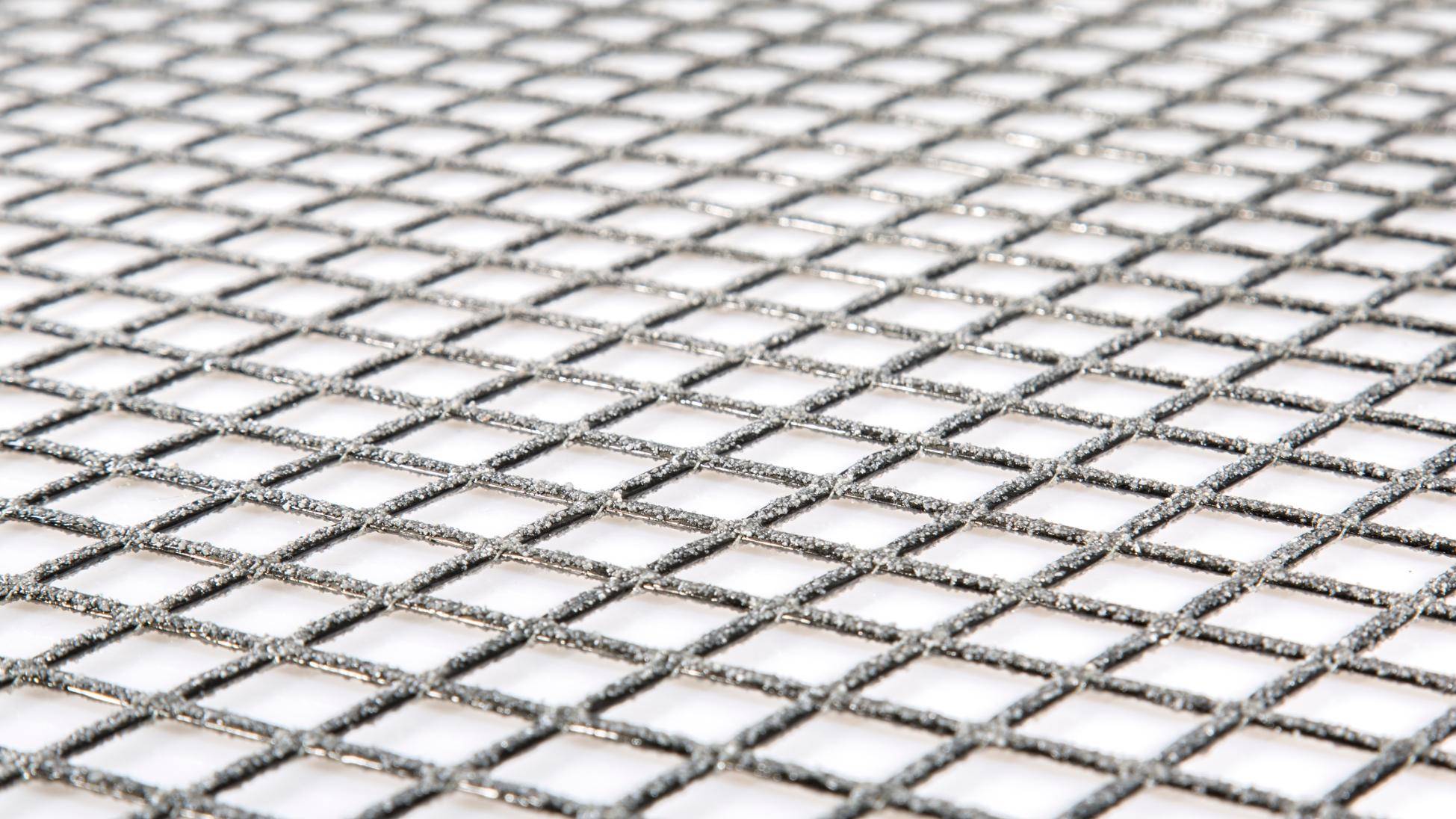
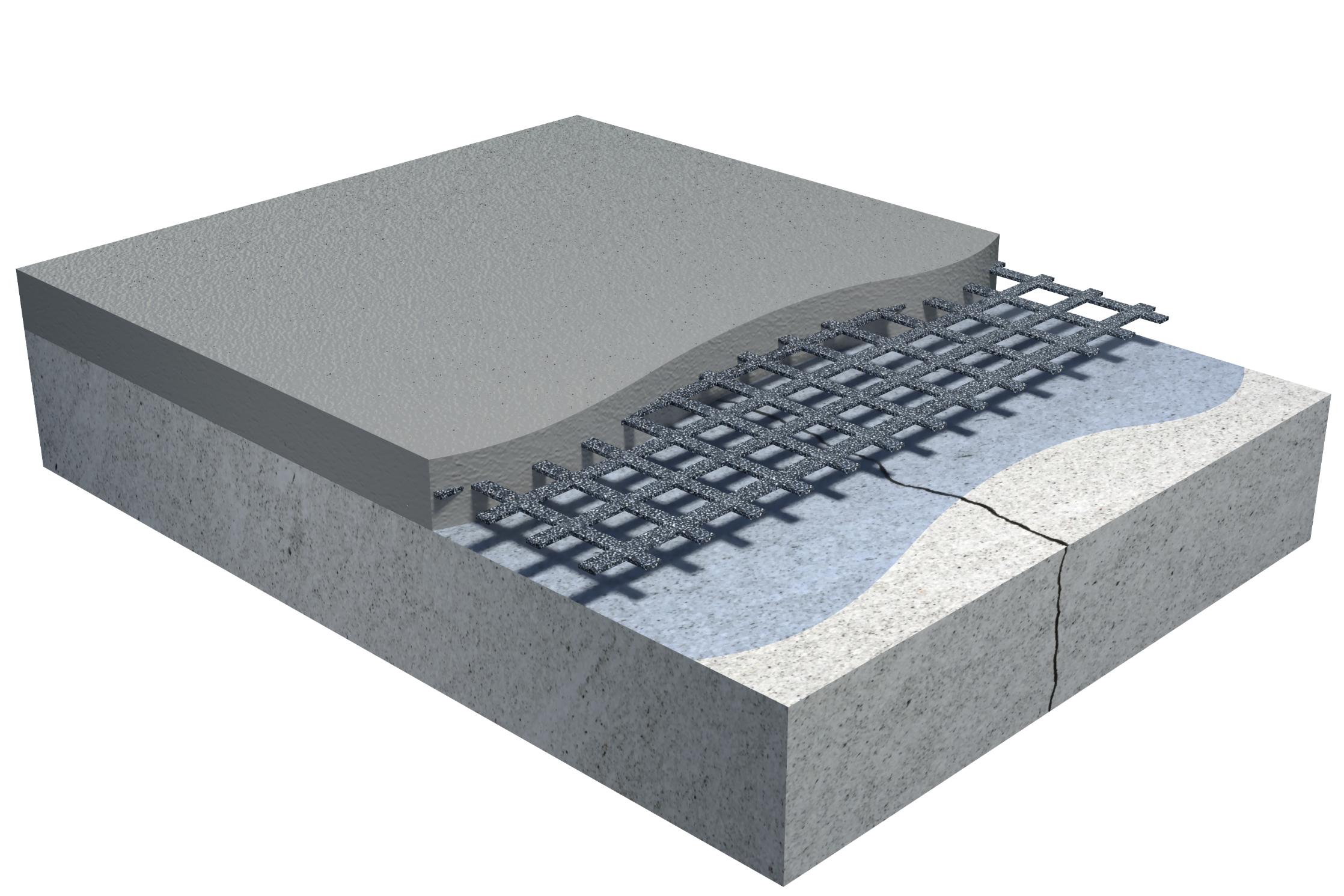
The fact that carbon reinforcement absorbs tensile stresses in a mortar layer and distributes cracks is the working principle (→ Part 1). The fact that this effect can be achieved with layer build-ups starting at 30 mm is the construction advantage (→ Part 2). What is equally important for planners, tendering bodies and checking engineers is this: the performance can be quantified.
From working principle to calculation basis
In concrete repair, a qualitative description of how a system works is rarely enough. Planners must be able to demonstrate to clients, operators and checking engineers that a system verifiably performs the intended function.
solidian ANTICRACK Q85-CCE-21 provides a technical basis for this. Based on crack-opening tests carried out by solidian, a characteristic stress-crack opening relationship is available for known mortar-grid combinations. This characteristic curve describes which crack width occurs at a specific reinforcement stress within the system.
This turns a working principle into a calculation basis.
The basis for crack-width estimation
The approximate assessment of crack width for a known system configuration follows a structured approach. The input parameters are:
• the thickness of the repair layer
• the effective tensile strength of the mortar used
• the nominal cross-sectional area of the carbon reinforcement
The nominal cross-sectional area of solidian ANTICRACK Q85-CCE-21 is 210 mm²/m.
These parameters can be used to determine the cracking force at the point of crack formation. From this, the reinforcement stress σnm is obtained. Based on the characteristic stress-crack opening relationship, the corresponding crack width w can then be read.
Model limitation: The calculation considers the repair layer as a discrete, independent layer — without taking into account any contribution from the bond to the existing substrate. The bond between the reprofiling mortar and the existing concrete is not included in the estimate, as no suitable calculation model for this interaction is currently available. The estimate therefore provides a conservative planning basis that represents the real system condition on the safe side.
Planning principles, evaluation diagrams and calculation examples for known system configurations are available from solidian on request.
What measurable crack widths mean for planning
For qualified repair planners and structural engineers, this means that crack-width limitation is no longer just a general system statement. It becomes a value that can be planned and verified.
In tender documents, requirement-specific crack widths can be defined. During execution, compliance can be traced through the selected system configuration. This is particularly relevant when subsequent coatings have a defined crack-bridging capacity — and when this capacity should not be exceeded by the mortar layer.
Crack-width estimation provides the basis for verifying repair concepts at system level and communicating them objectively to operators and clients.
What this means for durability
Controlled crack widths extend the service life of subsequent coating systems. A coating applied to a low-crack, mechanically stable mortar layer is exposed to lower stresses than a coating applied to a surface with uncontrolled cracking.
In addition, the carbon reinforcement itself is corrosion-free:
• no chloride-induced or carbonation-related reinforcement corrosion
• no spalling caused by the volume increase of corroding reinforcement
• no corrosion-related consequential damage to the repair layer
The manufacturer-stated material durability of the carbon grid is more than 100 years. This is not only a material argument — it is a system argument for repairs with a long planned functional service life.
Economic planning reliability for operators
Plannable crack widths lead to plannable service lives. Plannable service lives lead to calculable maintenance costs. For operators of parking decks, infrastructure and industrial surfaces, this means:
• extended repair intervals due to a more durable mortar layer and coating
• lower lifecycle costs through reduced repeated repair measures
• higher surface availability due to fewer interruptions of use
• better planning reliability for operation and maintenance budgets
The corrosion resistance of the system permanently eliminates corrosion-related damage caused by the reinforcement itself — a factor that directly contributes to lifecycle cost assessment when planning repairs with a long functional service life.
Technical data – solidian ANTICRACK Q85-CCE-21
| Characteristic | Value |
|---|---|
| Reinforcement type | Symmetrical, bidirectional, type Q |
| Nominal cross-sectional area | 210 mm²/m |
| Weight | < 1 kg/m² |
| System layer thickness | possible from 30 mm |
| Corrosion resistance | fully resistant to chlorides and carbonation |
| Material durability | more than 100 years, according to manufacturer’s statement |
| Roll coverage | up to 260 m² per unit |
| Delivery forms |
individual grid 6.0 m × 2.30 m; roll material up to 115 m × 2.30 m |
Conclusion of the series
solidian ANTICRACK Q85-CCE-21 does three things at the same time: it explains its working principle in a technically understandable way (→ Part 1), enables thin layer build-ups without compromising corrosion protection (→ Part 2), and provides a basis for quantifiable crack-width estimation (Part 3).
This makes it a system that not only works on site, but also stands up in planning, tendering and discussions with operators and clients.
Ready to discuss your project?
To support planners, we offer an extensive planning center with relevant documents and a structural dimensioning tool. If you are evaluating reinforcement options for a specific repair project, our technical team can help review the relevant parameters and documentation.
Bereit, Ihr Projekt zu besprechen?
Zur Unterstützung von Planern bieten wir ein umfassendes Planungscenter mit relevanten Dokumenten und einem Bemessungstool. Wenn Sie Bewehrungsoptionen für ein konkretes Instandsetzungsprojekt prüfen, unterstützt Sie unser technisches Team gerne bei der Bewertung der relevanten Parameter und Dokumentation.